4 驱动调试
4.1 电源配置
RK GPIO编号说明
A组: A0-A7对应0-7B组: B0-B7对应8-15C组: C0-C7对应16-23D组: D0-D7对应24-31GPIO编号计算方法:
例如:GPIO4_C4 = 4*32+16+4 = 148
4.1.1 查看原理图
4.1.2 获取需要的配置信息,并在dts里配置
通过查看原理图,获取到相应的信息,然后在dts里配置
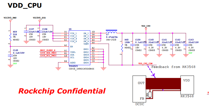
1、RK809和TCS4525是挂在I2C0下。输出电压VDD_CPU为0.9V, dts配置如下
vdd_cpu: tcs4525@1c { compatible = “tcs,tcs452x”; reg = <0x1c>; vin-supply = <&vcc5v0_sys>; regulator-compatible = “fan53555-reg”; regulator-name = “vdd_cpu”; … regulator-init-microvolt = <900000>; … };2、RK809各输入电压的输入源
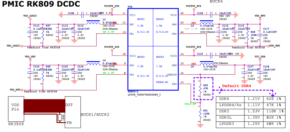
输入电压输入源VCC1VCC5V0_SYSVCC2VCC5V0_SYSVCC3VCC5V0_SYSVCC4VCC5V0_SYSVCC5VCC3V3_SYSVCC6VCC3V3_SYSVCC7VCC3V3_SYSVCC8VCC3V3_SYSVCC9VCC3V3_SYSdts配置如下:
vcc1-supply = <&vcc5v0_SYS>; vcc2-supply = <&vcc5v0_SYS>; vcc3-supply = <&vcc5v0_SYS>; vcc4-supply = <&vcc5v0_SYS>; vcc5-supply = <&vcc3v3_sys>; vcc6-supply = <&vcc3v3_sys>; vcc7-supply = <&vcc3v3_sys>; vcc8-supply = <&vcc3v3_sys>; vcc9-supply = <&vcc3v3_sys>;通过查看原理图,VCC5V0_SYS是底板给的,VCC3V3_SYS是由VCC5V0_SYS转的
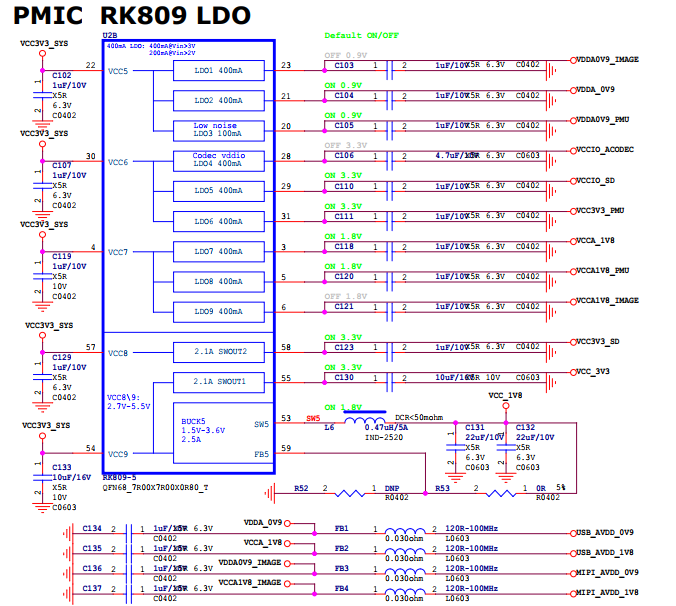
3、RK809输出电压名及其电压值
电源名称电压值BUCK1VDD_LOGIC0.9VBUCK2VDD_GPU0.9VBUCK3VCC_DDR硬件调节BUCK4VDD_NPU0.9VLDO1VDDA0V9_IMAGE0.9VLDO2VDDA_0V90.9VLDO3VDDA0V9_PMU0.9VLDO4VCCIO_ACODEC3.3VLDO5VCCIO_SD1.8-3.3VLDO6VCC3V3_PMU3.3VLDO7VCCA_1V81.8VLDO8VCCA1V8_PMU1.8VLDO9VCCA1V8_IMAGE1.8VSWCUT1VCC_3V33.3VSWCUT2VCC3V3_SD3.3VBUCK5VCC_1V81.8Vdts里配置
regulators { vdd_logic: DCDC_REG1 { regulator-always-on; regulator-boot-on; regulator-min-microvolt = <500000>; regulator-max-microvolt = <1350000>; regulator-init-microvolt = <900000>; regulator-ramp-delay = <6001>; regulator-initial-mode = <0x2>; regulator-name = “vdd_logic”; regulator-state-mem { regulator-off-in-suspend; }; }; vdd_gpu: DCDC_REG2 { regulator-always-on; regulator-boot-on; regulator-min-microvolt = <500000>; regulator-max-microvolt = <1350000>; regulator-init-microvolt = <900000>; regulator-ramp-delay = <6001>; regulator-initial-mode = <0x2>; regulator-name = “vdd_gpu”; regulator-state-mem { regulator-off-in-suspend; }; }; vcc_ddr: DCDC_REG3 { regulator-always-on; regulator-boot-on; regulator-initial-mode = <0x2>; regulator-name = “vcc_ddr”; regulator-state-mem { regulator-on-in-suspend; }; }; vdd_npu: DCDC_REG4 { regulator-always-on; regulator-boot-on; regulator-min-microvolt = <500000>; regulator-max-microvolt = <1350000>; regulator-init-microvolt = <900000>; regulator-ramp-delay = <6001>; regulator-initial-mode = <0x2>; regulator-name = “vdd_npu”; regulator-state-mem { regulator-off-in-suspend; }; }; vdda0v9_image: LDO_REG1 { regulator-boot-on; regulator-always-on; regulator-min-microvolt = <900000>; regulator-max-microvolt = <900000>; regulator-name = “vdda0v9_image”; regulator-state-mem { regulator-off-in-suspend; }; }; vdda_0v9: LDO_REG2 { regulator-always-on; regulator-boot-on; regulator-min-microvolt = <900000>; regulator-max-microvolt = <900000>; regulator-name = “vdda_0v9”; regulator-state-mem { regulator-off-in-suspend; }; }; vdda0v9_pmu: LDO_REG3 { regulator-always-on; regulator-boot-on; regulator-min-microvolt = <900000>; regulator-max-microvolt = <900000>; regulator-name = “vdda0v9_pmu”; regulator-state-mem { regulator-on-in-suspend; regulator-suspend-microvolt = <900000>; }; }; vccio_acodec: LDO_REG4 { regulator-always-on; regulator-boot-on; regulator-min-microvolt = <3300000>; regulator-max-microvolt = <3300000>; regulator-name = “vccio_acodec”; regulator-state-mem { regulator-off-in-suspend; }; }; vccio_sd: LDO_REG5 { regulator-always-on; regulator-boot-on; regulator-min-microvolt = <1800000>; regulator-max-microvolt = <3300000>; regulator-name = “vccio_sd”; regulator-state-mem { regulator-off-in-suspend; }; }; vcc3v3_pmu: LDO_REG6 { regulator-always-on; regulator-boot-on; regulator-min-microvolt = <3300000>; regulator-max-microvolt = <3300000>; regulator-name = “vcc3v3_pmu”; regulator-state-mem { regulator-on-in-suspend; regulator-suspend-microvolt = <3300000>; }; }; vcca_1v8: LDO_REG7 { regulator-always-on; regulator-boot-on; regulator-min-microvolt = <1800000>; regulator-max-microvolt = <1800000>; regulator-name = “vcca_1v8”; regulator-state-mem { regulator-off-in-suspend; }; }; vcca1v8_pmu: LDO_REG8 { regulator-always-on; regulator-boot-on; regulator-min-microvolt = <1800000>; regulator-max-microvolt = <1800000>; regulator-name = “vcca1v8_pmu”; regulator-state-mem { regulator-on-in-suspend; regulator-suspend-microvolt = <1800000>; }; }; vcca1v8_image: LDO_REG9 { regulator-always-on; regulator-boot-on; regulator-min-microvolt = <1800000>; regulator-max-microvolt = <1800000>; regulator-name = “vcca1v8_image”; regulator-state-mem { regulator-off-in-suspend; }; }; vcc_1v8: DCDC_REG5 { regulator-always-on; regulator-boot-on; regulator-min-microvolt = <1800000>; regulator-max-microvolt = <1800000>; regulator-name = “vcc_1v8”; regulator-state-mem { regulator-off-in-suspend; }; }; vcc_3v3: SWITCH_REG1 { regulator-always-on; regulator-boot-on; regulator-name = “vcc_3v3”; regulator-state-mem { regulator-off-in-suspend; }; }; vcc3v3_sd: SWITCH_REG2 { regulator-always-on; regulator-boot-on; regulator-name = “vcc3v3_sd”; regulator-state-mem { regulator-off-in-suspend; }; }; }; 在原有配置的基础上增加、删除、修改4 驱动调试 在原有配置的基础上增加、删除、修改4.1 电源配置 RK GPIO编号说明 A组: A0-A7对应0-7 B组: B0-B7对应8-15 C组: C0-C7对应16-23 D组: D0-D7对应24-31 GPIO编号计算方法: 例如:GPIO4_C4 = 4*32+16+4 = 148 4.1.1 查看原理图 4.1.2 获取需要的配置信息,并在dts里配置 通过查看原理图,获取到相应的信息,然后在dts里配置 1、RK809和TCS4525是挂在I2C0下。输出电压VDD_CPU为0.9V, dts配置如下 vdd_cpu: tcs4525@1c { compatible = “tcs,tcs452x”; reg = <0x1c>; vin-supply = <&vcc5v0_sys>; regulator-compatible = “fan53555-reg”; regulator-name = “vdd_cpu”; … regulator-init-microvolt = <900000>; … }; 2、RK809各输入电压的输入源 | 输入电压 | 输入源 | | ————- | —————- | | VCC1 | VCC5V0_SYS | | VCC2 | VCC5V0_SYS | | VCC3 | VCC5V0_SYS | | VCC4 | VCC5V0_SYS | | VCC5 | VCC3V3_SYS | | VCC6 | VCC3V3_SYS | | VCC7 | VCC3V3_SYS | | VCC8 | VCC3V3_SYS | | VCC9 | VCC3V3_SYS | dts配置如下: vcc1-supply = <&vcc5v0_SYS>; vcc2-supply = <&vcc5v0_SYS>; vcc3-supply = <&vcc5v0_SYS>; vcc4-supply = <&vcc5v0_SYS>; vcc5-supply = <&vcc3v3_sys>; vcc6-supply = <&vcc3v3_sys>; vcc7-supply = <&vcc3v3_sys>; vcc8-supply = <&vcc3v3_sys>; vcc9-supply = <&vcc3v3_sys>; 通过查看原理图,VCC5V0_SYS是底板给的,VCC3V3_SYS是由VCC5V0_SYS转的 3、RK809输出电压名及其电压值 | | 电压名称 | 电压值 | | ———-| —————— | —————| | BUCK1 | VDD_LOGIC | 0.9V | | BUCK2 | VDD_GPU | 0.9V | | BUCK3 | VCC_DDR | 硬件调节 | | BUCK4 | VDD_NPU | 0.9V | | LDO1 | VDDA0V9_IMAGE| 0.9V | | LDO2 | VDDA_0V9 | 0.9V | | LDO3 | VDDA0V9_PMU | 0.9V | | LDO4 | VCCIO_ACODEC | 3.3V | | LDO5 | VCCIO_SD | 1.8-3.3V | | LDO6 | VCC3V3_PMU | 3.3V | | LDO7 | VCCA_1V8 | 1.8V | | LDO8 | VCCA1V8_PMU | 1.8V | | LDO9 | VCCA1V8_IMAGE| 1.8V | | SWCUT1 | VCC_3V3 | 3.3V | | SWCUT2 | VCC3V3_SD | 3.3V | | BUCK5 | VCC_1V8 | 1.8V | dts里配置 regulators { vdd_logic: DCDC_REG1 { regulator-always-on; regulator-boot-on; regulator-min-microvolt = <500000>; regulator-max-microvolt = <1350000>; regulator-init-microvolt = <900000>; regulator-ramp-delay = <6001>; regulator-initial-mode = <0x2>; regulator-name = “vdd_logic”; regulator-state-mem { regulator-off-in-suspend; }; }; vdd_gpu: DCDC_REG2 { regulator-always-on; regulator-boot-on; regulator-min-microvolt = <500000>; regulator-max-microvolt = <1350000>; regulator-init-microvolt = <900000>; regulator-ramp-delay = <6001>; regulator-initial-mode = <0x2>; regulator-name = “vdd_gpu”; regulator-state-mem { regulator-off-in-suspend; }; }; vcc_ddr: DCDC_REG3 { regulator-always-on; regulator-boot-on; regulator-initial-mode = <0x2>; regulator-name = “vcc_ddr”; regulator-state-mem { regulator-on-in-suspend; }; }; vdd_npu: DCDC_REG4 { regulator-always-on; regulator-boot-on; regulator-min-microvolt = <500000>; regulator-max-microvolt = <1350000>; regulator-init-microvolt = <900000>; regulator-ramp-delay = <6001>; regulator-initial-mode = <0x2>; regulator-name = “vdd_npu”; regulator-state-mem { regulator-off-in-suspend; }; }; vdda0v9_image: LDO_REG1 { regulator-boot-on; regulator-always-on; regulator-min-microvolt = <900000>; regulator-max-microvolt = <900000>; regulator-name = “vdda0v9_image”; regulator-state-mem { regulator-off-in-suspend; }; }; vdda_0v9: LDO_REG2 { regulator-always-on; regulator-boot-on; regulator-min-microvolt = <900000>; regulator-max-microvolt = <900000>; regulator-name = “vdda_0v9”; regulator-state-mem { regulator-off-in-suspend; }; }; vdda0v9_pmu: LDO_REG3 { regulator-always-on; regulator-boot-on; regulator-min-microvolt = <900000>; regulator-max-microvolt = <900000>; regulator-name = “vdda0v9_pmu”; regulator-state-mem { regulator-on-in-suspend; regulator-suspend-microvolt = <900000>; }; }; vccio_acodec: LDO_REG4 { regulator-always-on; regulator-boot-on; regulator-min-microvolt = <3300000>; regulator-max-microvolt = <3300000>; regulator-name = “vccio_acodec”; regulator-state-mem { regulator-off-in-suspend; }; }; vccio_sd: LDO_REG5 { regulator-always-on; regulator-boot-on; regulator-min-microvolt = <1800000>; regulator-max-microvolt = <3300000>; regulator-name = “vccio_sd”; regulator-state-mem { regulator-off-in-suspend; }; }; vcc3v3_pmu: LDO_REG6 { regulator-always-on; regulator-boot-on; regulator-min-microvolt = <3300000>; regulator-max-microvolt = <3300000>; regulator-name = “vcc3v3_pmu”; regulator-state-mem { regulator-on-in-suspend; regulator-suspend-microvolt = <3300000>; }; }; vcca_1v8: LDO_REG7 { regulator-always-on; regulator-boot-on; regulator-min-microvolt = <1800000>; regulator-max-microvolt = <1800000>; regulator-name = “vcca_1v8”; regulator-state-mem { regulator-off-in-suspend; }; }; vcca1v8_pmu: LDO_REG8 { regulator-always-on; regulator-boot-on; regulator-min-microvolt = <1800000>; regulator-max-microvolt = <1800000>; regulator-name = “vcca1v8_pmu”; regulator-state-mem { regulator-on-in-suspend; regulator-suspend-microvolt = <1800000>; }; }; vcca1v8_image: LDO_REG9 { regulator-always-on; regulator-boot-on; regulator-min-microvolt = <1800000>; regulator-max-microvolt = <1800000>; regulator-name = “vcca1v8_image”; regulator-state-mem { regulator-off-in-suspend; }; }; vcc_1v8: DCDC_REG5 { regulator-always-on; regulator-boot-on; regulator-min-microvolt = <1800000>; regulator-max-microvolt = <1800000>; regulator-name = “vcc_1v8”; regulator-state-mem { regulator-off-in-suspend; }; }; vcc_3v3: SWITCH_REG1 { regulator-always-on; regulator-boot-on; regulator-name = “vcc_3v3”; regulator-state-mem { regulator-off-in-suspend; }; }; vcc3v3_sd: SWITCH_REG2 { regulator-always-on; regulator-boot-on; regulator-name = “vcc3v3_sd”; regulator-state-mem { regulator-off-in-suspend; }; }; };<
免责声明:文章内容来自互联网,本站不对其真实性负责,也不承担任何法律责任,如有侵权等情况,请与本站联系删除。
转载请注明出处:RK3568开发板安卓系统之驱动调试(四)-rk3328开发板 https://www.yhzz.com.cn/a/9770.html