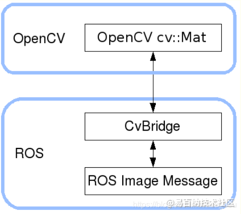
ROS无法直接进行图像处理,需要借助于opencv,要使用cv_bridge把ROS 的图像数据格式转为Opencv可以使用的数据格式。即是一个提供ROS和OpenCV库提供之间的接口的开发包。然后可以将opencv处理好的图像再转换回ros中的数据格式。
 包含的头文件如下:
#include<stdio.h>#include<stdlib.h>#include<iostream>#include<opencv2/opencv.hpp>#include“opencv2/highgui/highgui.hpp”#include<ros/ros.h>#include<cv_bridge/cv_bridge.h>#include<image_transport/image_transport.h>
包含的头文件如下:
#include<stdio.h>#include<stdlib.h>#include<iostream>#include<opencv2/opencv.hpp>#include“opencv2/highgui/highgui.hpp”#include<ros/ros.h>#include<cv_bridge/cv_bridge.h>#include<image_transport/image_transport.h>
从主函数开始:
int main(int argc,char** argv ){//初始化节点 ros::init(argc, argv,“simple_grasping_vision_detection”);//创建节点句柄 ros::NodeHandle n_;//输出等待2s.. ROS_INFO_STREAM(“Waiting for two seconds..”); ros::WallDuration(2.0).sleep();float length =0.3;float breadth =0.3;//创建一个VisionManager类的对象VisionManager vm(n_, length, breadth);while(ros::ok()){// Process image callback ros::spinOnce(); ros::WallDuration(2.0).sleep();}return0;}首先初始化节点,节点名为simple_grasping_vision_detection,创建一个VisionManager类的对象vm,然后再循环中不断的进行处理。 看一下类的构造函数:
VisionManager::VisionManager(ros::NodeHandle n_,float length,float breadth): it_(n_){this->table_length = length;this->table_breadth = breadth;// Subscribe to input video feed and publish object location image_sub_ = it_.subscribe(“/probot_anno/camera/image_raw”,1,&VisionManager::imageCb,this); image1_pub_ = it_.advertise(“/table_detect”,1); image2_pub_ = it_.advertise(“/object_detect”,1);}构造函数输入有三个形参,VisionManager::VisionManager(ros::NodeHandle n, float length, float breadth): ros::NodeHandle n 是节点句柄; float length 是 float breadth 是 然后订阅了摄像头发布信息的话题,imagesub = it.subscribe(“/probot_anno/camera/image_raw”, 1, &VisionManager::imageCb, this); 发布两个话题,一个是检测到的桌面,image1_pub = it.advertise(“/table_detect”, 1);另外一个是检测到的物体,image2_pub = it_.advertise(“/object_detect”, 1); 当订阅者接收到图像之后就会进入到回调函数当中:
voidVisionManager::imageCb(const sensor_msgs::ImageConstPtr&msg){ ROS_INFO_STREAM(“Processing the Image to locate the Object…”);// ROS_INFO(“Image Message Received”);float obj_x, obj_y; get2DLocation(msg, obj_x, obj_y);// Temporary Debugging std::cout<<” X-Co-ordinate in Camera Frame :”<< obj_x << std::endl; std::cout<<” Y-Co-ordinate in Camera Frame :”<< obj_y << std::endl;}回调函数中先打印一条信息显示要开始识别,然后调用另外一个函数 get2DLocation进行识别,最后将识别的结果输出。obj_x, obj_y为最终目标的具体位置。 看一下get2DLocation函数的识别过程:
voidVisionManager::get2DLocation(const sensor_msgs::ImageConstPtr&msg,float&x,float&y){ cv::Rect tablePos; detectTable(msg, tablePos); detect2DObject(msg, x, y, tablePos); convertToMM(x, y);}在这个函数当中,首先使用detectTable(msg, tablePos)函数去识别table,函数的形参分别为输入的图像msg和table的位置tablePos。然后再使用detect2DObject(msg, x, y, tablePos)函数识别目标,该函数识别目标的范围是只在前一个函数检测到桌面的范围内识别。最后使用convertToMM(x, y)函数将检测到目标的像素位置转换成实际的位置。所以识别桌子有两个目的,第一个是为了所以识别目标的范围,第二个是为了从桌子识别的尺寸来确定目标真实目标的大小与像素大小的对应关系。 这函数真实一环一环又一环,一套一套又一套。 桌面识别: 下面看一下桌面识别:
voidVisionManager::detectTable(const sensor_msgs::ImageConstPtr&msg, cv::Rect&tablePos){// Extract Table from the image and assign values to pixel_per_mm fields//从图像中提取表并将值赋给pixel_per_mm字段 cv::Mat BGR[3];try{ cv_ptr_ = cv_bridge::toCvCopy(msg, sensor_msgs::image_encodings::BGR8);}catch(cv_bridge::Exception&e){ ROS_ERROR(“cv_bridge exception: %s”, e.what());return;} cv::Mat&image = cv_ptr_->image; split(image, BGR); cv::Mat gray_image_red = BGR[2]; cv::Mat gray_image_green = BGR[1]; cv::Mat denoiseImage; cv::medianBlur(gray_image_red, denoiseImage,3);// Threshold the Image cv::Mat binaryImage = denoiseImage;for(int i =0; i < binaryImage.rows; i++){for(int j =0; j < binaryImage.cols; j++){int editValue = binaryImage.at<uchar>(i, j);int editValue2 = gray_image_green.at<uchar>(i, j);if((editValue >=0)&&(editValue <20)&&(editValue2 >=0)&&(editValue2 <20)){// check whether value is within range. binaryImage.at<uchar>(i, j)=255;}else{ binaryImage.at<uchar>(i, j)=0;}}} dilate(binaryImage, binaryImage, cv::Mat());// Get the centroid of the of the blob std::vector<cv::Point> nonZeroPoints; cv::findNonZero(binaryImage, nonZeroPoints); cv::Rect bbox = cv::boundingRect(nonZeroPoints); cv::Point pt; pt.x = bbox.x + bbox.width /2; pt.y = bbox.y + bbox.height /2; cv::circle(image, pt,4, cv::Scalar(0,0,255),–1,8);// Update pixels_per_mm fields pixels_permm_y = bbox.height / table_length; pixels_permm_x = bbox.width / table_breadth; tablePos = bbox;// Test the conversion values std::cout <<“Pixels in y”<< pixels_permm_y << std::endl; std::cout <<“Pixels in x”<< pixels_permm_x << std::endl;// Draw Contours – For Debugging std::vector<std::vector<cv::Point>> contours; std::vector<cv::Vec4i> hierarchy; cv::findContours(binaryImage, contours, hierarchy, CV_RETR_TREE, CV_CHAIN_APPROX_SIMPLE, cv::Point(0,0));for(int i =0; i < contours.size(); i++){ cv::Scalar color = cv::Scalar(255,0,0); cv::drawContours(image, contours, i, color,3,8, hierarchy,0, cv::Point());}// Output modified video stream image1_pub_.publish(cv_ptr_->toImageMsg());}使用try…catch函数将ros中的图像数据通过cvbridge转化成opencv格式的数据,主要的语句为:cv_ptr = cv_bridge::toCvCopy(msg, sensor_msgs: :BGR8); 接下来将RGB图像的红色和绿色两个通道分离出来:
medianBlur函数为进行中值滤波。 下面的for循环是为了在红色和绿色两个通道中确认黑色桌子的位置,然后将桌子位置的点像素值设置为255,其他地方位置的像素值设置为0。
for(int i =0; i < binaryImage.rows; i++){for(int j =0; j < binaryImage.cols; j++){int editValue = binaryImage.at<uchar>(i, j);int editValue2 = gray_image_green.at<uchar>(i, j);//如果像素点在红色通道中的阈值在0-20之间并且在绿色通道中阈值也在0-20之间,那么就判断为黑色if((editValue >=0)&&(editValue <20)&&(editValue2 >=0)&&(editValue2 <20)){// check whether value is within range. binaryImage.at<uchar>(i, j)=255;}else{ binaryImage.at<uchar>(i, j)=0;}}}接下来找桌面的中心位置,只需要先找像素值非零的位置:cv::findNonZero(binaryImage, nonZeroPoints); 再通过boundingRect函数计算轮廓的垂直边界最小矩形,矩形是与图像上下边界平行的。 然后根据框的位置计算出桌面的中心点位置:
cv::Point pt;
pt.x = bbox.x + bbox.width / 2;
pt.y = bbox.y + bbox.height / 2;
//在中心点画一个红色的圈圈
cv::circle(image, pt, 4, cv::Scalar(0, 0, 255), -1, 8);
计算桌子的实际尺寸与像素尺寸的对应比例关系:
//table_length是桌子实际的长,bbox.height是像素长度
pixels_permm_y = bbox.height / table_length;//table_length是桌子实际的宽,bbox.height是像素宽度
pixels_permm_x = bbox.width / table_breadth;
画一个蓝色的框框出桌子的轮廓: // Draw Contours – For Debugging std::vector<std::vector<cv::Point>> contours; std::vector<cv::Vec4i> hierarchy; cv::findContours(binaryImage, contours, hierarchy, CV_RETR_TREE, CV_CHAIN_APPROX_SIMPLE, cv::Point(0,0));for(int i =0; i < contours.size(); i++){ cv::Scalar color = cv::Scalar(255,0,0); cv::drawContours(image, contours, i, color,3,8, hierarchy,0, cv::Point());}最后将识别到的结果先变为ROS中的图像格式,然后发布出去:
image1_pub_.publish(cv_ptr_->toImageMsg());物体识别: 在绿色通道中对阈值进行识别,可以很容易的识别出绿色的易拉罐位置:
voidVisionManager::detect2DObject(const sensor_msgs::ImageConstPtr&msg,float&pixel_x,float&pixel_y, cv::Rect&tablePos){// Implement Color Thresholding and contour findings to get the location of object to be grasped in 2D cv::Mat gray_image_green; cv::Mat BGR[3];try{ cv_ptr_ = cv_bridge::toCvCopy(msg, sensor_msgs::image_encodings::BGR8);}catch(cv_bridge::Exception&e){ ROS_ERROR(“cv_bridge exception: %s”, e.what());return;} cv::Mat&image = cv_ptr_->image; cv::split(image, BGR); gray_image_green = BGR[1];// Denoise the Image cv::Mat denoiseImage; cv::medianBlur(gray_image_green, denoiseImage,3);// Threshold the Image cv::Mat binaryImage = denoiseImage;for(int i =0; i < binaryImage.rows; i++){for(int j =0; j < binaryImage.cols; j++){if((j<tablePos.x+3)|| j>(tablePos.x+tablePos.width–3)||(i<tablePos.y+3)|| i>(tablePos.y + tablePos.height–3)){ binaryImage.at<uchar>(i, j)=0;}else{int editValue = binaryImage.at<uchar>(i, j);if((editValue >100)&&(editValue <=255)){// check whether value is within range. binaryImage.at<uchar>(i, j)=255;}else{ binaryImage.at<uchar>(i, j)=0;}}}} dilate(binaryImage, binaryImage, cv::Mat());// Get the centroid of the of the blob std::vector<cv::Point> nonZeroPoints; cv::findNonZero(binaryImage, nonZeroPoints); cv::Rect bbox = cv::boundingRect(nonZeroPoints); cv::Point pt; pixel_x = bbox.x + bbox.width /2; pixel_y = bbox.y + bbox.height /2;// Test the conversion values std::cout <<“pixel_x”<< pixel_x << std::endl; std::cout <<“pixel_y”<< pixel_y << std::endl;// For Drawing pt.x = bbox.x + bbox.width /2; pt.y = bbox.y + bbox.height /2; cv::circle(image, pt,4, cv::Scalar(0,0,255),–1,8);// Draw Contours std::vector<std::vector<cv::Point>> contours; std::vector<cv::Vec4i> hierarchy; cv::findContours(binaryImage, contours, hierarchy, CV_RETR_TREE, CV_CHAIN_APPROX_SIMPLE, cv::Point(0,0));for(int i =0; i < contours.size(); i++){ cv::Scalar color = cv::Scalar(255,0,0); cv::drawContours(image, contours, i, color,3,8, hierarchy,0, cv::Point());}// Output modified video stream image2_pub_.publish(cv_ptr_->toImageMsg());}计算目标中心位置 将物体的中心点位置进行变换,计算出中心位置相对于摄像头采集到图像的中心位置的左标(以中心点为(0,0)坐标原点)
voidVisionManager::convertToMM(float&x,float&y){ img_centre_x_ =640/2; img_centre_y_ =480/2;// Convert from pixel to world co-ordinates in the camera frame x =(x – img_centre_x_)/ pixels_permm_x; y =(y – img_centre_y_)/ pixels_permm_y;}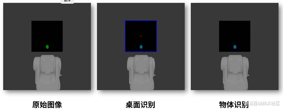
免责声明:文章内容来自互联网,本站不对其真实性负责,也不承担任何法律责任,如有侵权等情况,请与本站联系删除。
转载请注明出处:在ROS中基于颜色做简单的物体识别-ros image view https://www.yhzz.com.cn/a/8681.html