复制//***Initialize UART for SIM900**//voidInitialize_SIM900(void)
{
//****Setting I/O pins for UART****//
TRISC6 = 0; // TX Pin set as output
TRISC7 = 1; // RX Pin set as input//________I/O pins set __________///**Initialize SPBRG register for required
baud rate and set BRGH for fast baud_rate**/
SPBRG = 129; //SIM900 operates at 9600 Baud rate so 129
BRGH = 1; // for high baud_rate//_________End of baud_rate setting_________////****Enable Asynchronous serial port*******//
SYNC = 0; // Asynchronous
SPEN = 1; // Enable serial port pins//_____Asynchronous serial port enabled_______////**Lets prepare for transmission & reception**//
TXEN = 1; // enable transmission
CREN = 1; // enable reception//__UART module up and ready for transmission and reception__////**Select 8-bit mode**//
TX9 = 0; // 8-bit reception selected
RX9 = 0; // 8-bit reception mode selected//__8-bit mode selected__//
}
//________UART module Initialized__________//
复制//**Function to send one byte of date to UART**//void_SIM900_putch(char bt)
{
while(!TXIF); // hold the program till TX buffer is free
TXREG = bt; //Load the transmitter buffer with the received value
}
//_____________End of function________________////**Function to get one byte of date from UART**//
char _SIM900_getch()
{
if(OERR) // check for Error
{
CREN = 0; //If error -> Reset
CREN = 1; //If error -> Reset
}
while(!RCIF); // hold the program till RX buffer is freereturn RCREG; //receive the value and send it to main function
}
//_____________End of function________________////**Function to convert string to byte**//voidSIM900_send_string(char* st_pt)
{
while(*st_pt) //if there is a char
_SIM900_putch(*st_pt++); //process it as a byte data
}
//___________End of function______________////**End of modified Codes**//void_SIM900_print(unsigned const char *ptr) {
while (*ptr != 0) {
_SIM900_putch(*ptr++);
}
复制do
{
Lcd_Set_Cursor(2,1);
Lcd_Print_String(“Module not found”);
}while (!SIM900_isStarted()); //wait till the GSM to send back “OK”Lcd_Set_Cursor(2,1);
Lcd_Print_String(“Module Detected “);
__delay_ms(1500);
复制/*Check if the SIM card is detected*/do
{
Lcd_Set_Cursor(2,1);
Lcd_Print_String(“SIM not found “);
}while (!SIM900_isReady()); //wait till the GSM to send back “+CPIN: READY”Lcd_Set_Cursor(2,1);
Lcd_Print_String(“SIM Detected “);
__delay_ms(1500);
复制/*Place a Phone Call*/do
{
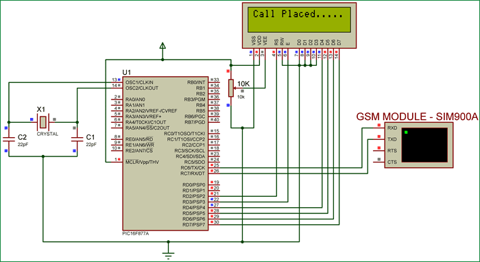
_SIM900_print(“ATD93643XXXXX;\\r\\n”); //Here we are placing a call to number 93643XXXXXLcd_Set_Cursor(1,1);
Lcd_Print_String(“Placing Call….”);
}while (_SIM900_waitResponse() != SIM900_OK); //wait till the ESP send back “OK”Lcd_Set_Cursor(1,1);
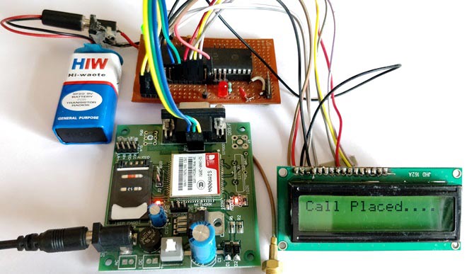
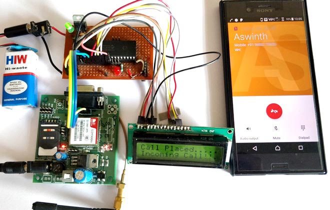
Lcd_Print_String(“Call Placed….”);
__delay_ms(1500);
发出呼叫后,液晶屏将显示“呼叫已发出”,您应该会收到该指定号码的来电。
您还可以拨打连接到GSM模块的手机号码,并使用以下代码在LCD屏幕上获得通知
复制while(1)
{
if (_SIM900_waitResponse() == SIM900_RING) //Check if there is an incoming call
{
Lcd_Set_Cursor(2,1);
Lcd_Print_String(“Incoming Call!!.”);
}
}
复制// CONFIG#pragma config FOSC = HS // Oscillator Selection bits (HS oscillator)#pragma config WDTE = OFF // Watchdog Timer Enable bit (WDT disabled)#pragma config PWRTE = OFF // Power-up Timer Enable bit (PWRT enabled)#pragma config BOREN = OFF // Brown-out Reset Enable bit (BOR enabled)#pragma config LVP = OFF // Low-Voltage (Single-Supply) In-Circuit Serial Programming Enable bit (RB3 is digital I/O, HV on MCLR must be used for programming)#pragma config CPD = OFF // Data EEPROM Memory Code Protection bit (Data EEPROM code protection off)#pragma config WRT = OFF // Flash Program Memory Write Enable bits (Write protection off; all program memory may be written to by EECON control)#pragma config CP = OFF // Flash Program Memory Code Protection bit (Code protection off)//End of CONFIG registers#define _XTAL_FREQ 20000000#define RS RD2#define EN RD3#define D4 RD4#define D5 RD5#define D6 RD6#define D7 RD7#define SIM900_OK 1#define SIM900_READY 2#define SIM900_FAIL 3#define SIM900_RING 4#define SIM900_NC 5#define SIM900_UNLINK 6#include// Wait for any response on the inputinlineunsignedchar _SIM900_waitResponse(void);
int recv;
char p =1;
//LCD Functions Developed by Circuit Digest.voidLcd_SetBit(char data_bit)//Based on the Hex value Set the Bits of the Data Lines{
if(data_bit& 1)
D4 = 1;
else
D4 = 0;
if(data_bit& 2)
D5 = 1;
else
D5 = 0;
if(data_bit& 4)
D6 = 1;
else
D6 = 0;
if(data_bit& 8)
D7 = 1;
else
D7 = 0;
}
voidLcd_Cmd(char a){
RS = 0;
Lcd_SetBit(a); //Incoming Hex value
EN = 1;
__delay_ms(4);
EN = 0;
}
voidLcd_Clear(){
Lcd_Cmd(0); //Clear the LCDLcd_Cmd(1); //Move the curser to first position
}
voidLcd_Set_Cursor(char a, char b){
char temp,z,y;
if(a== 1)
{
temp = 0x80 + b – 1; //80H is used to move the curser
z = temp>>4; //Lower 8-bits
y = temp & 0x0F; //Upper 8-bitsLcd_Cmd(z); //Set RowLcd_Cmd(y); //Set Column
}
elseif(a== 2)
{
temp = 0xC0 + b – 1;
z = temp>>4; //Lower 8-bits
y = temp & 0x0F; //Upper 8-bitsLcd_Cmd(z); //Set RowLcd_Cmd(y); //Set Column
}
}
voidLcd_Start(){
Lcd_SetBit(0x00);
for(int i=1065244; i<=0; i–) NOP();
Lcd_Cmd(0x03);
__delay_ms(5);
Lcd_Cmd(0x03);
__delay_ms(11);
Lcd_Cmd(0x03);
Lcd_Cmd(0x02); //02H is used for Return home -> Clears the RAM and initializes the LCDLcd_Cmd(0x02); //02H is used for Return home -> Clears the RAM and initializes the LCDLcd_Cmd(0x08); //Select Row 1Lcd_Cmd(0x00); //Clear Row 1 DisplayLcd_Cmd(0x0C); //Select Row 2Lcd_Cmd(0x00); //Clear Row 2 DisplayLcd_Cmd(0x06);
}
voidLcd_Print_Char(char data)//Send 8-bits through 4-bit mode{
char Lower_Nibble,Upper_Nibble;
Lower_Nibble = data&0x0F;
Upper_Nibble = data&0xF0;
RS = 1; // => RS = 1Lcd_SetBit(Upper_Nibble>>4); //Send upper half by shifting by 4
EN = 1;
for(int i=2130483; i<=0; i–) NOP();
EN = 0;
Lcd_SetBit(Lower_Nibble); //Send Lower half
EN = 1;
for(int i=2130483; i<=0; i–) NOP();
EN = 0;
}
voidLcd_Print_String(char *a){
int i;
for(i=0;a[i]!=\\0;i++)
Lcd_Print_Char(a[i]); //Split the string using pointers and call the Char function
}
/*****End of LCD Functions*****///***Initialize UART for SIM900**//voidInitialize_SIM900(void){
//****Setting I/O pins for UART****//
TRISC6 = 0; // TX Pin set as output
TRISC7 = 1; // RX Pin set as input//________I/O pins set __________///**Initialize SPBRG register for required
baud rate and set BRGH for fast baud_rate**/
SPBRG = 129; //SIM900 operates at 9600 Baud rate so 129
BRGH = 1; // for high baud_rate//_________End of baud_rate setting_________////****Enable Asynchronous serial port*******//
SYNC = 0; // Asynchronous
SPEN = 1; // Enable serial port pins//_____Asynchronous serial port enabled_______////**Lets prepare for transmission & reception**//
TXEN = 1; // enable transmission
CREN = 1; // enable reception//__UART module up and ready for transmission and reception__////**Select 8-bit mode**//
TX9 = 0; // 8-bit reception selected
RX9 = 0; // 8-bit reception mode selected//__8-bit mode selected__//
}
//________UART module Initialized__________////**Function to send one byte of date to UART**//void _SIM900_putch(char bt)
{
while(!TXIF); // hold the program till TX buffer is free
TXREG = bt; //Load the transmitter buffer with the received value
}
//_____________End of function________________////**Function to get one byte of date from UART**//char _SIM900_getch()
{
if(OERR) // check for Error
{
CREN = 0; //If error -> Reset
CREN = 1; //If error -> Reset
}
while(!RCIF); // hold the program till RX buffer is freereturn RCREG; //receive the value and send it to main function
}
//_____________End of function________________////**Function to convert string to byte**//voidSIM900_send_string(char* st_pt){
while(*st_pt) //if there is a char
_SIM900_putch(*st_pt++); //process it as a byte data
}
//___________End of function______________////**End of modified Codes**//void _SIM900_print(unsignedconstchar *ptr) {
while (*ptr != 0) {
_SIM900_putch(*ptr++);
}
}
bit SIM900_isStarted(void){
_SIM900_print(“AT\\r\\n”);
return (_SIM900_waitResponse() == SIM900_OK);
}
bit SIM900_isReady(void){
_SIM900_print(“AT+CPIN?\\r\\n”);
return (_SIM900_waitResponse() == SIM900_READY);
}
inlineunsignedchar _SIM900_waitResponse(void) {
unsignedchar so_far[6] = {0,0,0,0,0,0};
unsignedconstchar lengths[6] = {2,12,5,4,6,6};
unsignedconstchar* strings[6] = {“OK”, “+CPIN: READY”, “ERROR”, “RING”, “NO CARRIER”, “Unlink”};
unsignedconstchar responses[6] = {SIM900_OK, SIM900_READY, SIM900_FAIL, SIM900_RING, SIM900_NC, SIM900_UNLINK};
unsignedchar received;
unsignedchar response;
char continue_loop = 1;
while (continue_loop) {
received = _SIM900_getch();
for (unsignedchar i = 0; i < 6; i++) {
if (strings[i][so_far[i]] == received) {
so_far[i]++;
if (so_far[i] == lengths[i]) {
response = responses[i];
continue_loop = 0;
}
} else {
so_far[i] = 0;
}
}
}
return response;
}
voidmain(void){
//I/O Declarations//
TRISD = 0x00; //LCD pins on port D as output//End of I/O declaration//Lcd_Start(); //Initialize LCD Initialize_SIM900();//lets get our Serial ready for actionLcd_Set_Cursor(1,1);
Lcd_Print_String(“SIM900 & PIC”);
/*Check if the SIM900 communication is successful*/do
{
Lcd_Set_Cursor(2,1);
Lcd_Print_String(“Module not found”);
}while (!SIM900_isStarted()); //wait till the GSM to send back “OK”Lcd_Set_Cursor(2,1);
Lcd_Print_String(“Module Detected “);
__delay_ms(1500);
/*Check if the SIM card is detected*/do
{
Lcd_Set_Cursor(2,1);
Lcd_Print_String(“SIM not found “);
}while (!SIM900_isReady()); //wait till the GSM to send back “+CPIN: READY”Lcd_Set_Cursor(2,1);
Lcd_Print_String(“SIM Detected “);
__delay_ms(1500);
Lcd_Clear();
/*Place a Phone Call*/do
{
_SIM900_print(“ATD93643XXXXX;\\r\\n”); //Here we are placing a call to number 93643XXXXXLcd_Set_Cursor(1,1);
Lcd_Print_String(“Placing Call….”);
}while (_SIM900_waitResponse() != SIM900_OK); //wait till the ESP send back “OK”Lcd_Set_Cursor(1,1);
Lcd_Print_String(“Call Placed….”);
__delay_ms(1500);
while(1)
{
if (_SIM900_waitResponse() == SIM900_RING) //Check if there is an incoming call
{
Lcd_Set_Cursor(2,1);
Lcd_Print_String(“Incoming Call!!.”);
}
}
}