复制for (int i=0; i<20;i++) //Read value for 20 Times
{
adc=0;
adc=ADC_Read(4); //Read ADC
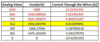
Voltage = adc*4.8828; //Calculate the Voltageif (Voltage>=2500) //If the current is positive
Amps += ((Voltage-2500)/18.5);
elseif (Voltage<=2500) //If the current is negative
Amps += ((2500-Voltage)/18.5);
}
Amps/=20; //Average the value that was read for 20 times
复制if (Voltage>=2500) //If the current is positive
Amps += ((Voltage-2500)/18.5);
else if (Voltage<=2500) //If the current is negative
Amps += ((2500-Voltage)/18.5);
复制if (Voltage>=2500) //If the current is positive
Amps += ((Voltage-2500)/0.66);
else if (Voltage<=2500) //If the current is negative
Amps += ((2500-Voltage)/0.66);
复制/*
Digital Ammeter for PIC16F877A
* Code by: B.Aswinth Raj
* Dated: 27-07-2017
* More details at: www.CircuitDigest.com
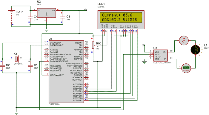
*/#define _XTAL_FREQ 20000000#define RS RD2#define EN RD3#define D4 RD4#define D5 RD5#define D6 RD6#define D7 RD7#include#pragma config FOSC = HS // Oscillator Selection bits (HS oscillator)#pragma config WDTE = OFF // Watchdog Timer Enable bit (WDT disabled)#pragma config PWRTE = ON // Power-up Timer Enable bit (PWRT enabled)#pragma config BOREN = ON // Brown-out Reset Enable bit (BOR enabled)#pragma config LVP = OFF // Low-Voltage (Single-Supply) In-Circuit Serial Programming Enable bit (RB3 is digital I/O, HV on MCLR must be used for programming)#pragma config CPD = OFF // Data EEPROM Memory Code Protection bit (Data EEPROM code protection off)#pragma config WRT = OFF // Flash Program Memory Write Enable bits (Write protection off; all program memory may be written to by EECON control)#pragma config CP = OFF // Flash Program Memory Code Protection bit (Code protection off)//LCD Functions Developed by Circuit Digest.voidLcd_SetBit(char data_bit)//Based on the Hex value Set the Bits of the Data Lines{
if(data_bit& 1)
D4 = 1;
else
D4 = 0;
if(data_bit& 2)
D5 = 1;
else
D5 = 0;
if(data_bit& 4)
D6 = 1;
else
D6 = 0;
if(data_bit& 8)
D7 = 1;
else
D7 = 0;
}
voidLcd_Cmd(char a){
RS = 0;
Lcd_SetBit(a); //Incoming Hex value
EN = 1;
__delay_ms(4);
EN = 0;
}
voidLcd_Clear(){
Lcd_Cmd(0); //Clear the LCDLcd_Cmd(1); //Move the curser to first position
}
voidLcd_Set_Cursor(char a, char b){
char temp,z,y;
if(a== 1)
{
temp = 0x80 + b – 1; //80H is used to move the curser
z = temp>>4; //Lower 8-bits
y = temp & 0x0F; //Upper 8-bitsLcd_Cmd(z); //Set RowLcd_Cmd(y); //Set Column
}
elseif(a== 2)
{
temp = 0xC0 + b – 1;
z = temp>>4; //Lower 8-bits
y = temp & 0x0F; //Upper 8-bitsLcd_Cmd(z); //Set RowLcd_Cmd(y); //Set Column
}
}
voidLcd_Start(){
Lcd_SetBit(0x00);
for(int i=1065244; i<=0; i–) NOP();
Lcd_Cmd(0x03);
__delay_ms(5);
Lcd_Cmd(0x03);
__delay_ms(11);
Lcd_Cmd(0x03);
Lcd_Cmd(0x02); //02H is used for Return home -> Clears the RAM and initializes the LCDLcd_Cmd(0x02); //02H is used for Return home -> Clears the RAM and initializes the LCDLcd_Cmd(0x08); //Select Row 1Lcd_Cmd(0x00); //Clear Row 1 DisplayLcd_Cmd(0x0C); //Select Row 2Lcd_Cmd(0x00); //Clear Row 2 DisplayLcd_Cmd(0x06);
}
voidLcd_Print_Char(char data)//Send 8-bits through 4-bit mode{
char Lower_Nibble,Upper_Nibble;
Lower_Nibble = data&0x0F;
Upper_Nibble = data&0xF0;
RS = 1; // => RS = 1Lcd_SetBit(Upper_Nibble>>4); //Send upper half by shifting by 4
EN = 1;
for(int i=2130483; i<=0; i–) NOP();
EN = 0;
Lcd_SetBit(Lower_Nibble); //Send Lower half
EN = 1;
for(int i=2130483; i<=0; i–) NOP();
EN = 0;
}
voidLcd_Print_String(char *a){
int i;
for(i=0;a[i]!=\\0;i++)
Lcd_Print_Char(a[i]); //Split the string using pointers and call the Char function
}
/*****End of LCD Functions*****///**ADC FUnctions***//voidADC_Initialize(){
ADCON0 = 0b01000001; //ADC ON and Fosc/16 is selected
ADCON1 = 0b11000000; // Internal reference voltage is selected
}
unsignedintADC_Read(unsignedchar channel){
ADCON0 &= 0x11000101; //Clearing the Channel Selection Bits
ADCON0 |= channel<<3; //Setting the required Bits
__delay_ms(2); //Acquisition time to charge hold capacitor
GO_nDONE = 1; //Initializes A/D Conversionwhile(GO_nDONE); //Wait for A/D Conversion to completereturn ((ADRESH<<8)+ADRESL); //Returns Result
}
//***End of ADC Functions***//intmain(){
int adc=0; //Variable to read ADC valueint a1,a2,a3,a4; //Variable to split ADC value into charint Voltage; //Variable to store voltageint vl1,vl2,vl3,vl4; //Variable to split Voltage value into charint Amps; //Variable to store Amps valueint Am1,Am2,Am3,Am4; //Variable to split Amps value into char
TRISD = 0x00; //PORTD declared as output for interfacing LCD
TRISA4 =1; //AN4 declared as inputADC_Initialize();
Lcd_Start();
Lcd_Clear();
while(1)
{
/***Current Calculation*****/for (int i=0; i<20;i++) //Read value for 20 Times
{
adc=0;
adc=ADC_Read(4); //Read ADC
Voltage = adc*4.8828; //Calculate the Voltageif (Voltage>=2500) //If the current is positive
Amps += ((Voltage-2500)/18.5);
elseif (Voltage<=2500) //If the current is negative
Amps += ((2500-Voltage)/18.5);
}
Amps/=20; //Average the value that was read for 20 times/******Current Calculation******///**Display current**//
Am1 = (Amps/100)%10;
Am2 = (Amps/10)%10;
Am3 = (Amps/1)%10;
Lcd_Set_Cursor(1,1);
Lcd_Print_String(“Current: “);
Lcd_Print_Char(Am1+0);
Lcd_Print_Char(Am2+0);
Lcd_Print_Char(.);
Lcd_Print_Char(Am3+0);
//**Display ADC**//
a1 = (adc/1000)%10;
a2 = (adc/100)%10;
a3 = (adc/10)%10;
a4 = (adc/1)%10;
Lcd_Set_Cursor(2,1);
Lcd_Print_String(“ADC:”);
Lcd_Print_Char(a1+0);
Lcd_Print_Char(a2+0);
Lcd_Print_Char(a3+0);
Lcd_Print_Char(a4+0);
//**Display Voltage**//
vl1 = (Voltage/1000)%10;
vl2 = (Voltage/100)%10;
vl3 = (Voltage/10)%10;
vl4 = (Voltage/1)%10;
Lcd_Print_String(” V:”);
Lcd_Print_Char(vl1+0);
Lcd_Print_Char(vl2+0);
Lcd_Print_Char(vl3+0);
Lcd_Print_Char(vl4+0);
}
return0;
}