OpenHarmony 分为轻量系统、小型系统、标准系统,目前对应 LiteOS-M、LiteOS-A、Linux 内核。但好像并没有说一定是按照使用内核来划分。我们这里姑且先这么区分。

本文使用的是比较新的 OpenHarmony 3.0 LTS 版本,Linux 内核,编译标准系统。
官方文档已经说明了,如何使用 DevEco Studio 开发 hap 包,并运行在开发板,但是 ACE 框架能力有限。
设备硬件开发还是需要 C,所以这篇文章,将在标准系统下编译 C 控制 Hi3516 开发板的 LED 闪烁。 
环境准备
3.0 源码下载: repo init -u https://gitee.com/openharmony/manifest.git -b OpenHarmony-3.0-LTS –no-repo-verify repo sync -c repo forall -c git lfs pull
区别于 2.0 需要安装 ruby,其他基本都一样。
sudo apt-get install ruby-full
编译命令:
build/prebuilts_download.sh ./build.sh –product-name Hi3516DV300
编写 helloworld.c
在 applications\standard 目录下新建一个 app 目录来存放 .c 的业务代码。
比如 applications\standard\app\helloworld.c 内容容下:
include int main(){ printf(“Hello world.\n”); return 0; }
然后在当前目录新建编译脚本 BUILD.gn 内容如下:
import(“//build/ohos.gni”) import(“//drivers/adapter/uhdf2/uhdf.gni”)
ohos_executable(“helloworld”) { sources = [ “helloworld.c” ] subsystem_name = “applications” part_name = “prebuilt_hap” }
然后添加到编译框架 applications\standard\hap\ohos.build 增加如下内容。
“//applications/standard/app:helloworld”
最后执行编译命令即可,开发板使用的是 Hi3516,在不指定 out 目录时,缺省生成在 /system/lib64 或 /system/lib 下。 
点亮开发板 LED
能打印 helloworld 说明环境是没问题的,接下来尝试点亮开发板的 LED。查看 Hi3516DV300 原理图: 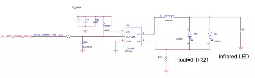

Hi3516DV300 共有 4 层板,由原理图可知:最上层板的红外补光灯接在 GPIO5_1,绿色 LED 指示灯在 GPIO2_3,核心板的红色 LED 在 GPIO3_4。
接下来参考 OpenHarmony GPIO 驱动说明:
https://gitee.com/openharmony/docs/blob/master/zh-cn/device-dev/driver/driver-platform-gpio-des.md
确定GPIO管脚号:不同SOC芯片由于其GPIO控制器型号、参数、以及控制器驱动的不同,GPIO管脚号的换算方式不一样。
①Hi3516DV300:控制器管理 12 组 GPIO 管脚,每组 8 个。
GPIO 号 = GPIO 组索引 (0~11) * 每组 GPIO 管脚数(8) + 组内偏移
举例:GPIO10_3 的 GPIO 号 = 10 * 8 + 3 = 83。
②Hi3518EV300:控制器管理 10 组 GPIO 管脚,每组 10 个。
GPIO 号 = GPIO 组索引 (0~9) * 每组 GPIO 管脚数(10) + 组内偏移
举例:GPIO7_3 的 GPIO 管脚号 = 7 * 10 + 3 = 73
由此可以得出: GPIO5_1 = 5 8 + 1; GPIO2_3 = 2 8 + 3; GPIO3_4 = 3 * 8 + 4;
然后新建 applications\standard\app\ledtest.c,内容如下:
include // standard library 标准库函数头文件 include // standard input output 标准输入输出函数 include // 定义了扩展的整数类型和宏
include // POSIX 系统 API 访问功能的头文件 include // unix标准中通用的头文件 define O_WRONLY and O_RDONLY
// #include define GPIO_DIR_IN “in” define GPIO_DIR_OUT “out” define GPIO_VAL_LOW 0 define GPIO_VAL_HIGHT 1
int32_t GpioSetDir(uint16_t gpio, char* dir){ char path[100] = {0}; sprintf(path,”echo %d > /sys/class/gpio/export”,gpio); system(path); printf(“info:%s\n”,path);
char direction[100] = {0}; sprintf(direction,”echo %s > /sys/class/gpio/gpio%d/direction”,dir,gpio); system(direction); printf(“info:%s\n”,direction); return 0;}
int32_t GpioWrite(uint16_t gpio, uint16_t val) { char path[100] = {0}; sprintf(path,”echo %d > /sys/class/gpio/gpio%d/value”,val,gpio); system(path); printf(“info:%s\n”,path); return 0; }
int main(){ uint16_t GPIO5_1 = 5 8 + 1; uint16_t GPIO2_3 = 2 8 + 3; uint16_t GPIO3_4 = 3 * 8 + 4;
printf(“LED test start\n”); int32_t ret; // uint16_t val; ret = GpioSetDir(GPIO5_1,GPIO_DIR_OUT); if (ret != 0) { printf(“GpioSerDir: failed, ret %d\n”, ret); return 0; } ret = GpioSetDir(GPIO2_3,GPIO_DIR_OUT); if (ret != 0) { printf(“GpioSerDir: failed, ret %d\n”, ret); return 0; } ret = GpioSetDir(GPIO3_4,GPIO_DIR_OUT); if (ret != 0) { printf(“GpioSerDir: failed, ret %d\n”, ret); return 0; } while(1) { GpioWrite(GPIO5_1, GPIO_VAL_HIGHT); usleep(1000000); GpioWrite(GPIO5_1, GPIO_VAL_LOW); usleep(1000000); GpioWrite(GPIO2_3, GPIO_VAL_HIGHT); usleep(1000000); GpioWrite(GPIO2_3, GPIO_VAL_LOW); usleep(1000000); GpioWrite(GPIO3_4, GPIO_VAL_HIGHT); usleep(1000000); GpioWrite(GPIO3_4, GPIO_VAL_LOW); usleep(1000000); } return 0;}
将业务代码添加到 BUILD.gn:
import(“//build/ohos.gni”) import(“//drivers/adapter/uhdf2/uhdf.gni”)
ohos_executable(“helloworld”) { sources = [ “helloworld.c” ] subsystem_name = “applications” part_name = “prebuilt_hap” }
ohos_executable(“ledtest”) { sources = [ “ledtest.c” ] subsystem_name = “applications” part_name = “prebuilt_hap” }
applications\standard\hap\ohos.build:
“//applications/standard/app:ledtest”
之后将程序烧录到开发板,执行 ./system/bin/ledtest: 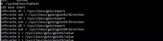
就可以看到 LED 闪烁起来了。
本来是打算使用鸿蒙的 GPIO 接口来实现这个功能的,不过调试了很久也没调通,最后无奈还是用的 system 自己实现的 GPIO 函数。
来源:鸿蒙技术社区
免责声明:文章内容来自互联网,本站不对其真实性负责,也不承担任何法律责任,如有侵权等情况,请与本站联系删除。
转载请注明出处:OpenHarmony 3.0上点亮开发板LED-开发板控制led灯怎么接线 https://www.yhzz.com.cn/a/11395.html