门控时钟单元分成两种,一种是带锁存器(latch based)的门控时钟单元,一种是不带有锁存器(latch free)的门控时钟单元。latch based的门控时钟单元能避免毛刺,因此更推荐使用。门控时钟又分为离散的和集成的(ICG)两种:
离散的CG单元1)带latch的CG(默认)set_clock_gating_style -sequential_cell latch
2)不带latch的CGset_clock_gating_style -sequential_cell none
集成的CG单元(ICG)set_clock_gating_style -negtive_edge_logic “integrated”
通常,在执行命令compile_ultra -gate_clock前需要设置好clock gating的相关配置选项,具体选项如下: set_clock_gating_style的options解析如下:
-sequential_cell none | latch
1) -sequential_cell latch(默认)
指带latch的CG(latch based style), 并可指定使用具体某个latch cell
比如:-sequential_celllatch:lib_cell。2) -sequential_cellnone
指不带latch的CG(latch free style),比如:
与门做CG,时钟使能为1时钟穿透AND,但posedge trigger存在毛刺;
或门做CG,时钟使能为0时钟穿透OR,但negesge trigger存在毛刺;
-minimum_bitwidth minsize_value
为了节省gating cell的数量,需达到一定寄存器数量的register bank才使用gating cell。
-setup setup_value 指定建立时间
-hold hold_value 指定保持时间-positive_edge_logic {cell_list | integrated [active_low_enable]
[invert_gclk]}
1) {cell_list}用于指定“上升沿”触发使用的CG单元。
需要注意的是-sequential_cell指定的是否有latch应该和cell_list的对应电路是否含有latch保持一致,如:set_clock_gating_style -sequential_cell latch -positive_edge_logic {latch and}
set_clock_gating_style -sequential_cell none -positive_edge_logic {or}
2) {integrated}用于表明使用上升沿触发的ICG单元。
如下图所示,该ICG单元就是一个pre-conctrolled positive-edge triggered clock gating latch。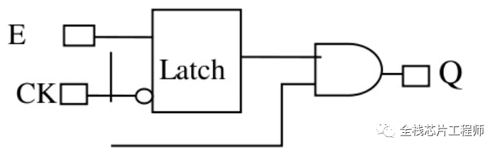
-negative_edge_logic {cell_list | integrated [active_low_enable]
[invert_gclk]}1) {cell_list}用于指定“下降沿”触发使用的CG单元。
需要注意的是-sequential_cell指定的是否有latch应该和cell_list的对应电路是否含有latch保持一致,如:set_clock_gating_style -sequential_cell latch -negtive_edge_logic {latch or}
set_clock_gating_style -sequential_cell none -negtive_edge_logic {and}
如下图,-sequential_cell none指定latch-free模式,但是cell_list却指定了latch、and/or, 这种情况下,DC工具仍然会综合出latch-based clock-gating的电路。


-control_point none | before | after对于DFT测试电路,为了满足电路可控,需要引入TE信号来控制latch的使能端。before就是在Latch之前插入或门,将TE信号和时钟使能信号或起来然后连接到Latch的D端。同理,after就是在Latch之后插入或门,将TE信号和Latch的Q端或起来然后连接到IGG的AND门。
-num_stages num_stages_count工具默认只使用一级门控时钟,而使用多级门控时钟可进一步节省面积、降低功耗。如下图,a信号被三个CG单元共享,那么将a信号做成第一级CG,b、c、d做成第二级CG。这样,增加了一个CG但减少了3个与门,同时节省了组合逻辑和第二级的CG的功耗。
set_clock_gating_style -num_stages 2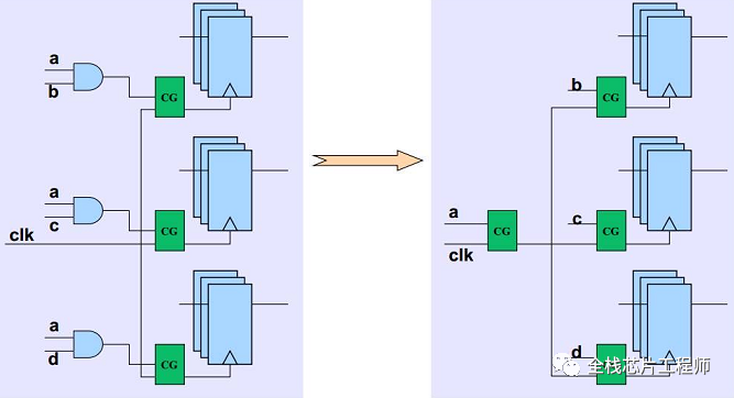
感谢阅读文章,如果文章有用,麻烦点个“在看”或转发分享。

转载:全栈芯片工程师
免责声明:文章内容来自互联网,本站不对其真实性负责,也不承担任何法律责任,如有侵权等情况,请与本站联系删除。
转载请注明出处:详解set_clock_gating_style命令-set_clock_gating_check https://www.yhzz.com.cn/a/11147.html